Building a Fluorescent Sound System
A (semi…) portable speaker for making a racket.
In 2014 I designed and built a portable “sound system” speaker. Although I’d built speaker cabinets before (building a box for some speaker drivers pulled from a scrapped car), I wanted to do this properly. That meant thick plywood to minimise vibration, high quality drivers and cabinets designed for good acoustic performance.
I wanted something which was portable enough to carry easily, but large enough for good sound output. It also needed to be capable of being driven by an internal battery. This meant class D amplifiers and a bi-amp topology with active crossovers for higher overall efficiency.
Design
I settled on a stereo design built into a single cabinet. A space in the middle would contain the amplifiers, crossovers and battery.
Driver selection
Selecting the main speaker driver was a trade off between portability (both weight and cabinet size), battery life, sound output and cost. Ultimately I went for a smaller driver (6" rather than 8") and a relatively large ported cabinet. I selected the Fane Sovereign 6-100, which I purchased from Blue Aran. It’s a 6" driver capable of handling 100W RMS.
Tweeter selection
Tweeter selection is slightly easier as tweeters don’t require a cabinet for acoustic performance. I selected the P-Audio PHT-413 for it’s high efficiency and low cost.
Speaker cabinet design
Speaker cabinet sizing makes a very large difference acoustically. I decided to build 2 small ported enclosures (these are also known as “bass reflex” enclosures). Introducing a port to a cabinet improves lower frequency performance at the cost of worse in-band amplitude flatness. The port provides a “bump” of increased loudness towards the bottom end of the speaker’s frequency response, followed by a much steeper roll off at low frequencies. The volume of air in the port (and so the port length and diameter) must be carefully selected based on the cabinet volume and main driver resonant frequency.
Fortunately there’s software which does much of the heavy lifting for you. I used an application called WinISD to model various speaker enclosure dimensions and port sizes, using the parameters for my driver.
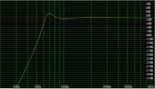
Ultimately I settled on a 75mm port. I found a cabinet with 17L of internal volume gave good results for my driver and port combination, with flat frequency response above 90 Hz, a 20 Hz wide 2dB spike between 70 and 90 Hz and a sharp roll off below (the 3dB point falls around 60 Hz). The plot below shows the computed gain response.
Case design
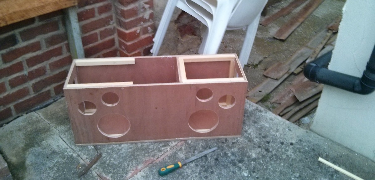
My aim was to build a single cabinet containing both the left and right speakers, with space between the two for batteries. I also wanted to build the design from a single sheet of 12mm plywood. The wood needed to be thick enough to avoid vibrations at low frequencies and as thin as possible to reduce weight.
The speaker cabinet needed to be approximately the target volume calculated in WinISD (with margin for all the components and the volume of the port). Standing waves can also be an issue in a speaker cabinet. Ensuring the dimensions in each direction are not equal (or exact multiples of each other) is good practice to mitigate constructive interference.
With the help of a spreadsheet I was able to tweak the dimensions of each component to maintain the required cabinet volume while also providing the desired storage space and limiting the overall dimensions of the speaker.
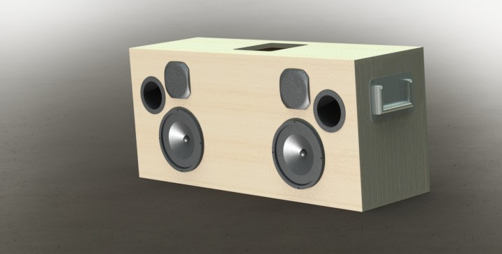
Once I had chosen the key dimensions, I modelled the speaker in Solidworks 3D CAD. By incorporating the main driver, tweeter and ports I could easily play with the layout to allow for part clearances and adjust the visual appearance of the speaker.
Building the case
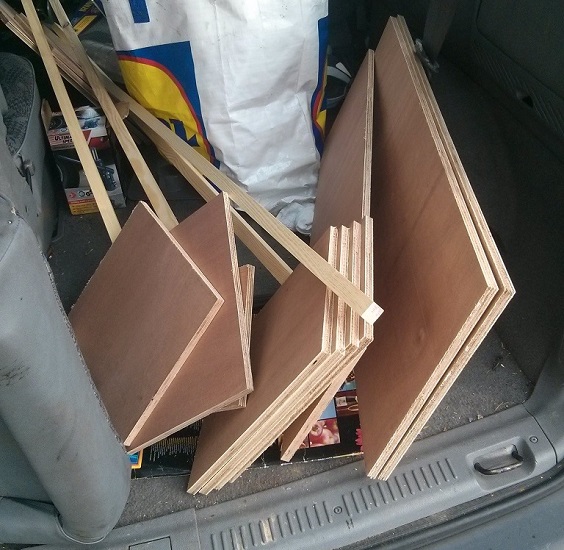
Once I’d settled on a final design in 3D CAD I needed to build it! I lay out the pieces onto a standard 1220x2440mm plywood sheet and had the supplier (a local builders merchant) slice it up on their table saw. Soon I had a car full of wood!
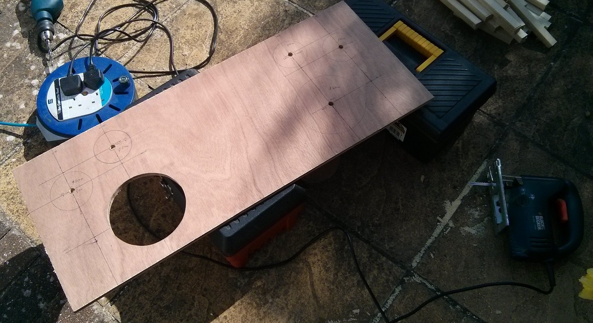
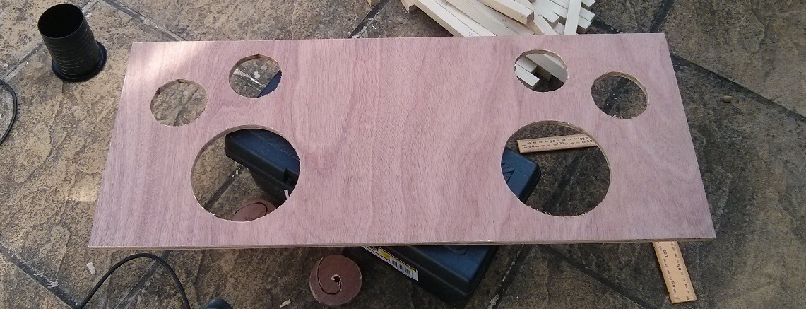
Assembly took place on a sunny sunday afternoon in my garden. I used a jigsaw to cut the (mostly) round holes for each driver.
I installed two fold out handles of the kind found on gig equipment, one on either end. Using these the speaker could be carried by one person. It’s rather heavy though!
Painting the case
I’m quite keen on fluorescent colours. Their ability to be brighter than life is quite amazing. I sketched some design concepts with some highlighters on some post it notes.
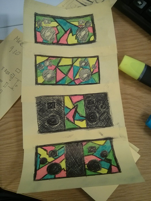
I went with the last one.
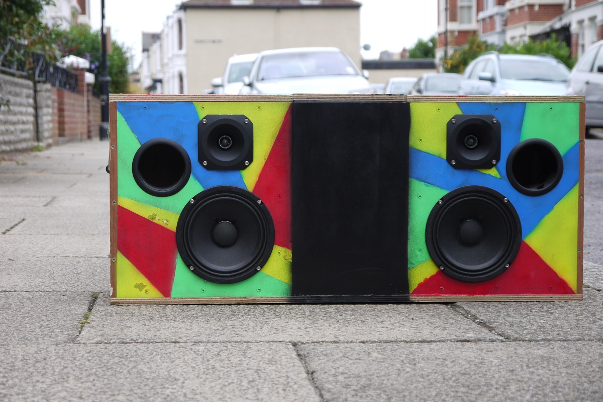
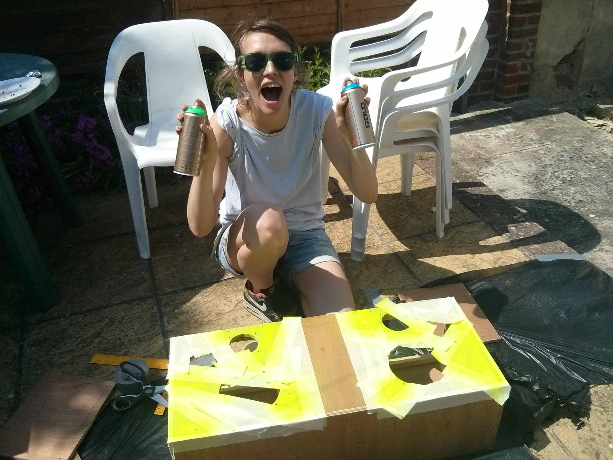
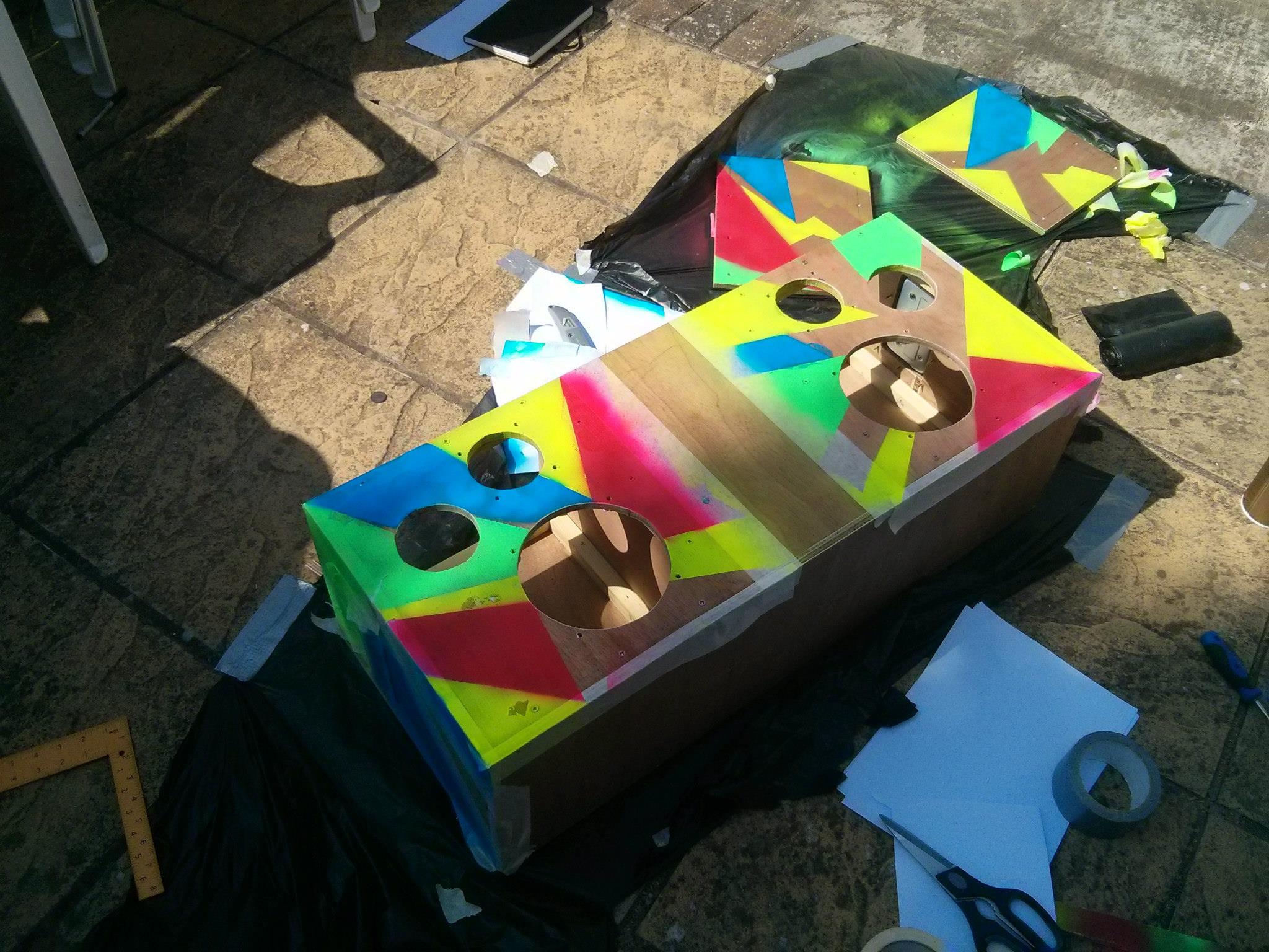
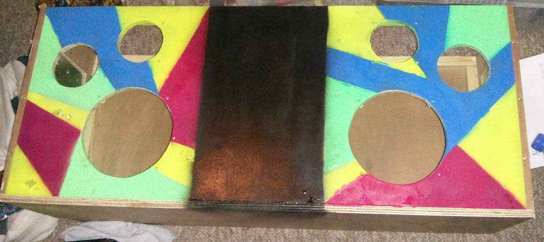
With the help of my girlfriend Anna I spent another sunny weekend painting the speaker. We masked off different jagged shapes and spray painted them with green, yellow, blue and pink fluorescent paint. This proved to be a slow process - if the paint hadn’t completely dried, peeling off the tape would cause it to flake off. After a long (but fun) process we had mostly finished the front and top! A bit of black paint around the edges finished it off. We ran out of paint before we could paint the sides - they’re currently unfinished plywood.
Amplifier selection
I wanted to use a class D (switching) amplifier for their lower power usage. Whereas more traditional linear amplifiers operate their transistors in the active region, generating a lot of heat in the process, a Class D amplifier uses pulses (turning the main transistor fully on or fully off) at high frequency to produce a pulse width modulated waveform at much higher efficiency. This makes them ideal for a battery powered system where power is very limited.
Fortunately there’s a lot of single chip class D amplifiers around. You can buy low cost generic boards from China which are essentially a particular chip’s reference design. Looking for something compact and able to operate on a single ended power supply, I bought a couple of TDA7498 boards for around £15 delivered. These are nominally capable of 80W RMS power output when supplied with 36 V, although in practice it’s probably less.
Cross over selection (DSP)
Given my aim for efficiency, a traditional passive crossover network seemed wasteful. I was intrigued by the concept of “bi-amp” speakers, in which a dedicated amplifier drives each speaker. This results in no complicated passive crossover network (with corresponding uncertainty in cross-over frequencies), instead requiring the signal to be low and high pass filtered at line level.
Active crossovers can either consist of dedicated analogue circuitry or a digital signal processor (DSP). Analogue circuitry has the advantage of simplicity and potentially low cost (although audio-level op-amps aren’t particularly cheap), while a DSP solution has the advantage of reconfigurability.
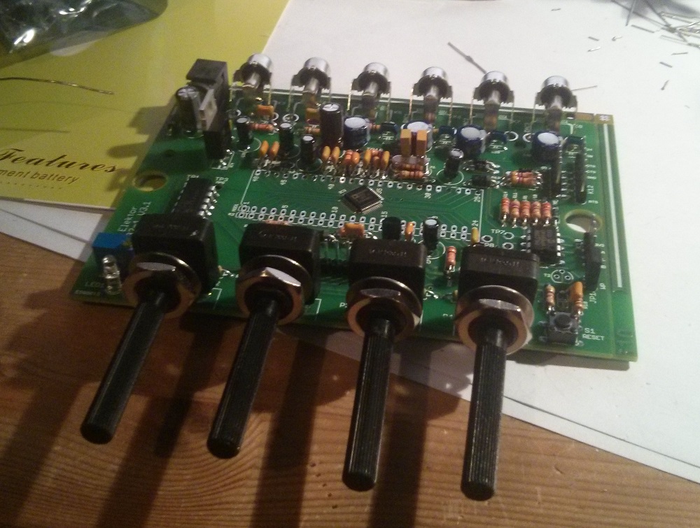
An interesting product on the market is the miniDSP - a board built around the Analog Devices ADAU1701 audio DSP chip. I liked the idea of that device, but the price tag was high and the very closed system (they additionally charge for each crossover design) put me off. I came across a kit designed by Elektor Magazine which was built around the same Analog Devices chip, but allowed you to use the free Analog Devices software tools for DSP design. As a bonus it was somewhat cheaper than a Mini-DSP.
Not a finished device, it required most components to be soldered by hand. This seemed like a nice challenge, so I bought one. A few hours of soldering later, and I had a crossover!
Power supply
Using a battery gave another problem. As an amplifier’s power output is basically dictated by the supply voltage (average power can be approximated as $$P_{RMS} = V^2/2R$$), I wanted to operate the chips at close to their maximum supply voltage. To do this I bought some low cost 35V boost converters. Nominally these are capable of 10A (150W), but I suspect they are able to sustain far less. I was concerned that these would significantly effect sound quality, but so far it seems like they don’t.
To drive the DSP I initially used a similar low cost buck converter. I found there was significant noise in the system, and so in the course of working to reduce this I replaced this with an isolated 5V DC-DC from XP Power.
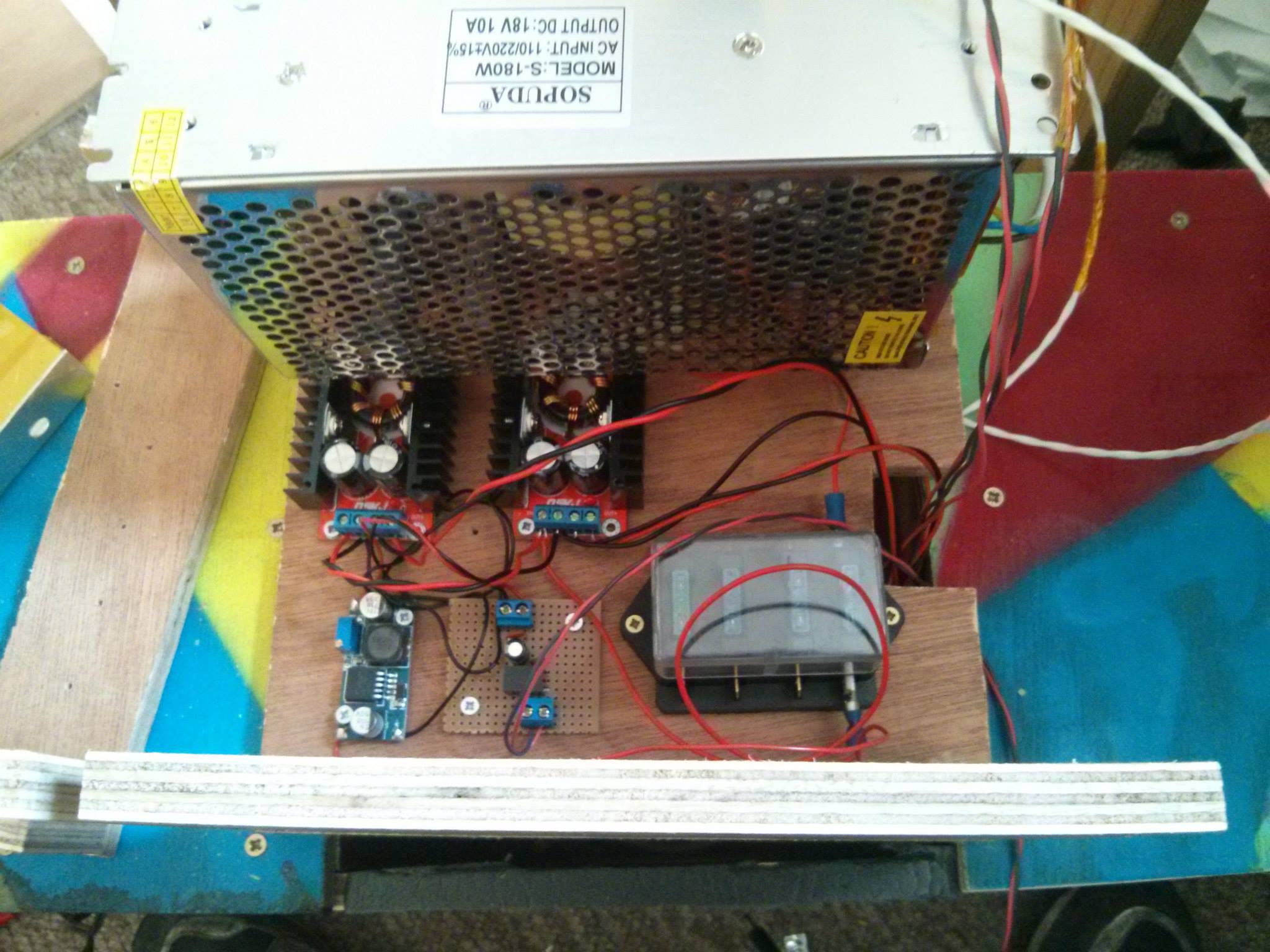 Mains power supply (top), 2x10A 35V boost converter (middle), 5V buck, 5V isolating DCDC, fuse box (bottom).
I also wanted to be able to operate on mains power while charging the battery at the same time. With this in mind I selected an 18 V mains power supply. This gave me enough head room to charge a lead acid battery while being suitable for the DC-DCs driving the amplifiers.
Dealing with noise in the system
When I connected it all up, there was a lot of humming. My initial worry was that there was switching noise coming from the very cheap 5V switching power supply driving the DSP. I replaced it with an isolating DC-DC converter from XP Power. This made a difference, but there was still hum.
It turns out a bi-amp configuration is particularly prone to ground loops because both the amplifiers and the crossover share a common ground. Unless they’re driven with isolated signals, a loop can form between the crossover and each amp. This loop can pick up low frequency RF signals which are introduced into the amplifier. I dealt with this by using an isolating audio transformer on the line input to the high frequency amplifier.
These two steps reduced the hum considerably.
Finished!
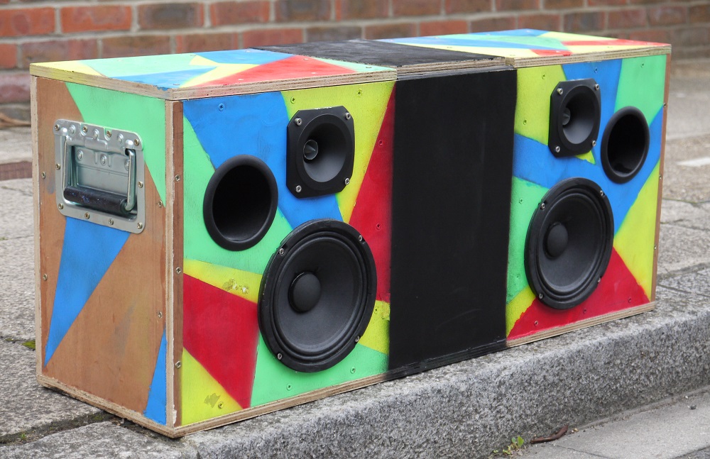
I keep meaning to finish painting the sides and back!