LED Light Control Board
After I built my LED sign (I discuss the process here), it became clear that simply turning the light on or off wasn’t enough. A few challenges were identified:
-
The light was too bright. At about 30 W of LEDs (which are far more efficient than a similarly rated incandescent would be), it puts out a lot of light. Not exactly mood lighting.
-
It needed to flash!
I decided to build something which addressed both of these. The concept was to build a microcontroller controlled circuit board with transistors for circuit switching. By driving the transistors with PWM outputs, any voltage between 0 and 12 V could be achieved. I found an interesting chip, the MSGEQ7, which provides an equaliser functionality, breaking down input audio into 7 frequencies. I try to describe the process I took in designing and building the board here.
Contents
Circuit Design
This was my fourth “proper” circuit board. I designed it using EAGLE.
Microcontroller Circuit
Anyone who’s used the Arduino platform will be aware of just how easy to use it is. The IDE is a little clunky, but the abstraction that it gives you over the AVR C++ makes projects fantastically easy. This project presented a chance to explore the concept of a barebones microcontroller on a circuit board. Rather than embed a full Arduino into every project, just putting a simple ATMega 328 and the crystal oscillator, capacitors, LED and resistor necessary is an easy way to save money.
I purchased the microcontroller and necessary components from ebay for about £4.50. The basic circuit required is discussed elsewhere, but boils down to a 16 MHz oscillator, two capacitors and (optionally) an LED and resistor. Programming can be done either by routing the pins required to a header or (simpler but more cumbersome) programming the chip on an Arduino and then placing it into a DIP socket. I chose this route for simplicity.
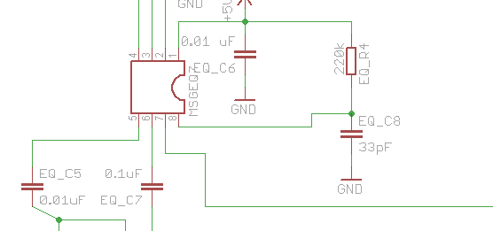
The Equaliser Chip
The MSGEQ7 is a very simple 8 pin chip which is connected to an audio source and outputs the intensity of each frequency as an analogue value. I purchased mine from the UK supplier Proto-Pic. A tutorial originally written by J Skoba and mirrored here details using it with an Arduino. I based my circuit design off both the tutorial and also the reference circuit in the chip datasheet (PDF).
EAGLE Circuit Design
click for the full schematic
It can be a little bit finicky at times, but EAGLE is a great way to design circuits. Designing a complicated circuit on paper is nearly impossible, and having a reference design to look at when you want to make a change is a godsend. I based my circuit off the aforementioned reference circuits. The full EAGLE files can be downloaded from Github.
Designing for stripboard in EAGLE can be a little complicated. There’s an excellent tutorial by Mike Perks which I’d recommend reading a few times if you’re looking to do similar things. If you have the facilities, getting a PCB etched (or doing it yourself) is much, much easier. Unfortunately online options were outside the budget of this project, and although it’s something I’d like to explore in the future I’m not yet equipped to do my own etching.
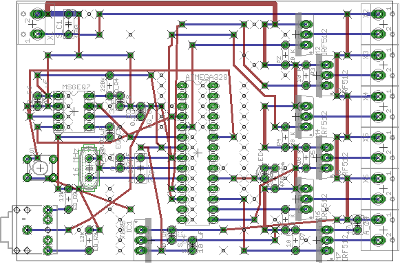
I placed the blue wires horizontally, representing the strips. A 0.1" grid was used. The red wires represent actual wires to be placed. When traces needed to be cut, I marked it with a hole. It took a lot of playing around to get a design which fitted on the board and didn’t have too many complicated wires.
Full Parts List
The parts I used for the final board are summarised here.
Barebones Arduino
- Atmel ATMega 328P (w/ Arduino bootloader) - datasheet, £4.50 from ebay
- 16 MHz Crystal Oscillator (came with ATMega) - like this
- 2 of 22 pF capacitors (came with ATMega)
- 2 mm yellow LED
- 470 K resistor
- Microswitch taken from a mouse
MSGEQ7 Equaliser
This is mostly from the example circuit in the datasheet. I used resistors that I already had, and so values are changed slightly.
- MSGEQ7 - datasheet, Sparkfun
- 2 of 10 nF capacitors
- 100 nF capacitor
- 33 pF capacitor
- 2 of 12 K resistors
- 220 K resistor
5V Voltage Regulator
- LM7805 linear regulator - datasheet
- 2 of 10 uF capacitors
Switching Transistors
The transistors I used were hugely overrated. Save some money and use ones that reflect the current you’ll see. The capacitor sizes are fairly arbitrary.
- 6 of N channel MOSFET (60V/30A) - datasheet, sparkfun
- 6 of 10 K pulldown resistors
- 100 uF capacitor (filtering)
- 47 uF capacitor (filtering)
- 7 0.1" pitch screw terminals (from ebay)
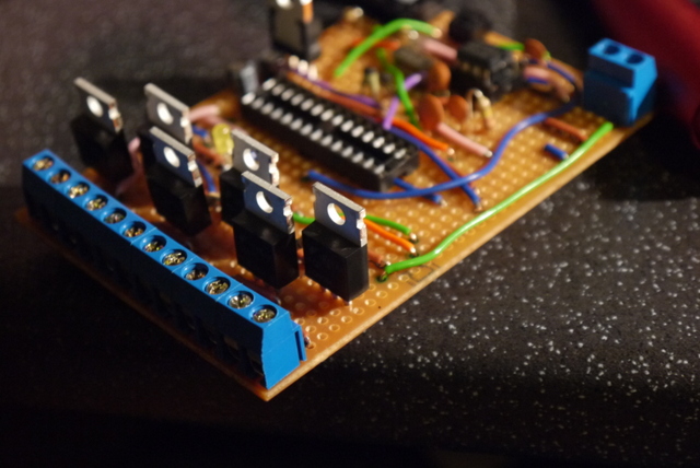
Making the Board
Stripboard is dull. It takes a long, long time to build up something.
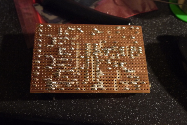
I started by making breaks in the traces. The easiest way to do this is to print out the hole layer of your board. If you mirror it (EAGLE displays from the top down, while we’re going to drill holes into the bottom) and print it to scale then you can simply line up the edges, tape the paper onto the board and get drilling.
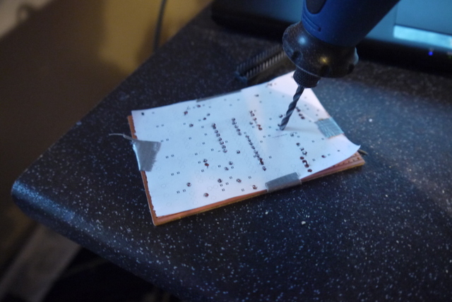
I used a dremel to mark each hole.
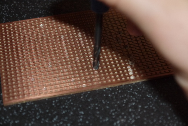
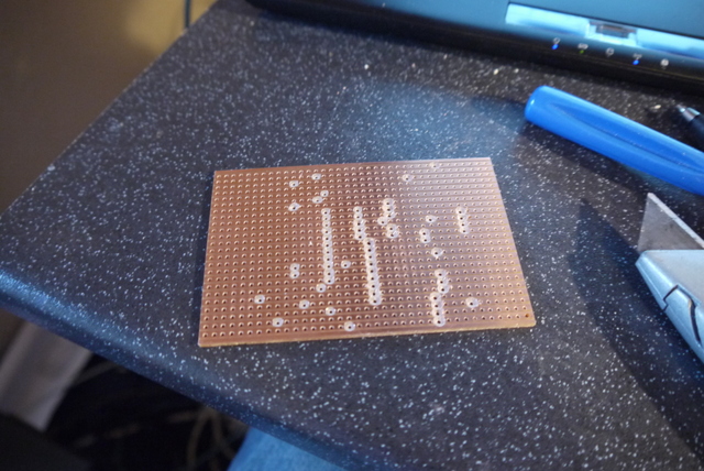
Then I cut each trace with a trace cutting tool (essentially a more ergonomic drill bit.)
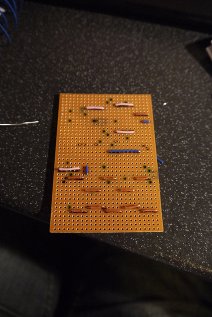
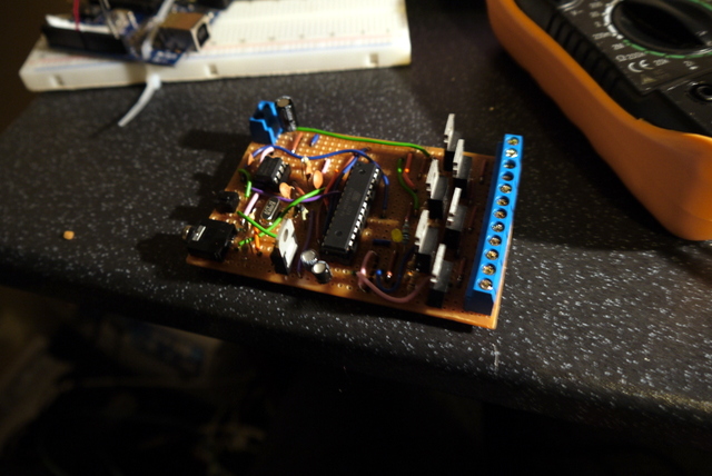
It’s easiest to place components in terms of height. I did wires first. Wires can be cut to length before you place them. If you cut ten at once, it saves a lot of time.
The wires were followed by the DIP sockets and small components. Then came the big components and the MOSFETs and 5 V regulator. Finally, I routed any wires that had to fit around other components.
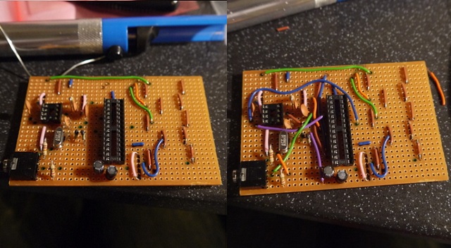
As the board starts to build up, placing things can get complicated. It helps if you have the original board layout available on a laptop.
Soldering can get quite tricky when you’re using the whole board. Patience and a good soldering iron are key.
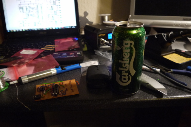
Eventually, you’ll be finished! It’s a long process - it took me Sunday afternoon and evening. I had a beer.
Mistakes and Corrections
This was my third EAGLE-designed stripboard. The more you make, the easier it becomes, but you’re still likely to make mistakes. I managed to place both DIP sockets the wrong way round. Not a crucial mistake, as long as you remember when you’re putting the chips in. I then dragged a Stanley knife between the strips to clear any loose solder. I used a multimeter to check both for unwanted shorts and that pins that should be connected were.
The two capacitors on the 12 V line were added after assembly. I found that the noise caused by PWM operation of the transistors was disrupting the microcontroller. The 100 uF capacitor by the 12 V input terminal mostly eliminated this issue, but proved to be too far away from the bottom transistor. A further 47 uF capacitor placed near the output completely fixed the problem.
The N channel MOSFETs I used are very overrated for the load. Each one is capable of switching 30 A, while my lights only pull about 3 A altogether. You could probably save some money by using smaller transistors.
I managed to snap a pin off the microcontroller as I removed it from a DIP socket. It means that one of my MOSFETs is no longer connected. As I only really need 2 of the 6 switching channels anyway, this isn’t much of a problem.
Software
I based my initial program off the one given in J Skoba’s tutorial. The program initialises the pins used, blinks the LED a couple of times and then turns the lights fully on. Pressing the button causes a counter to be advanced, leading to either a dimmed mode or a flashing mode. The full code (along with board schematics) is hosted on the project Github page.
Reading the MSGEQ7
This was really simplified by a tutorial by J Skoba. The code here is mostly his.
I first declared the pin variables and initialised them.
int analog_pin = 0; // read from multiplexer using analog input 0
int strobe_pin = 2; // strobe is attached to digital pin 2
int reset_pin = 4; // reset is attached to digital pin 3
int spectrum_value[7]; // to hold a2d values

void setup() {
    //define equaliser pins
    pinMode(analog_pin, INPUT);
    pinMode(strobe_pin, OUTPUT);
    pinMode(reset_pin, OUTPUT);
}
Each time the loop() function is run, the chip is reset. This is done by strobing the reset pin of the chip.
//reset the equaliser
digitalWrite(reset_pin, HIGH);
digitalWrite(reset_pin, LOW);
To actually read data from the chip, the strobe pin is made low and the analogue output of the analog pin is read.
//get equaliser values
for (int i = 0; i < 7; i++)
{
   digitalWrite(strobe_pin, LOW);
   delayMicroseconds(30); // to allow the output to settle
   spectrum_value[i] = analogRead(analog_pin);

   digitalWrite(strobe_pin, HIGH);
 }
Different Modes
I used a simple push switch taken from a mouse for mode changes. The internal pullup resistors are used, and the switch connects to ground when closed. A simple if statement checks each time the loop runs for switch connection. By also checking if it was connected last time we ran, the counter is only appended once for each push.
//This deals with the switch for settings. It increments the setting counter and blinks the LED on switch press.
if (digitalRead(switch_pin) == LOW) {
    if (switch_pin_pre == false) {
        if (setting_counter <7) setting_counter++;
        else setting_counter = 0;

        //blink once
        digitalWrite(led_pin, HIGH);
        delay(350);
        digitalWrite(led_pin,LOW);
        delay(350);
        switch_pin_pre = true;
    }
} else if (switch_pin_pre == true) {
   switch_pin_pre = false;
}
“Bounce” can be a problem with this type of switch, but didn’t seem to be here. One issue with this method of switch polling is that if your program main loop is quite long it can miss switch presses. Interrupts can be a solution to this. I added the switch as an afterthought and had already used the two interrupt-enabled pins on the microcontroller.
Finally, a switch/case statement is used to execute a different function depending on mode. The example given here sets a threshold for each frequency, and triggers the light if the audio level is above that threshold.
//The different flashing modes.
//Flash modes turn the light on or off depending on whether a threshold value has been reached.
switch (setting_counter) {

    /* Other modes here */

    case 4: //Flash mode 1

       /* get equaliser values (see above) */

       //need to find a way to filter this so that it yields better results
       //I've set everything but 3 to 400 as 500 seemed a little too thresholdy.
       if (spectrum_value[0] > 300) analogWrite(tr0_pin, 255);
       else analogWrite(tr0_pin, 0);
       if (spectrum_value[0] > 300) analogWrite(tr1_pin, 255);
       else analogWrite(tr1_pin, 0);
       if (spectrum_value[1] > 300) analogWrite(tr2_pin, 255);
       else analogWrite(tr2_pin, 0);
       if (spectrum_value[1] > 300) analogWrite(tr3_pin, 255);
       else analogWrite(tr3_pin, 0);
       if (spectrum_value[3] > 400) analogWrite(tr4_pin, 255);
       else analogWrite(tr4_pin, 0);
       if (spectrum_value[5] > 300) analogWrite(tr5_pin, 255);
       else analogWrite(tr5_pin, 0);
       break;
Testing
Primary issues were:
-
I didn’t have enough capacitance on the 12 V rail. When the circuit tried to switch quickly (ie anything other than off or on), the noise caused the microcontroller to reset. I added some capacitors (as in the EAGLE files) which fixed the issue.
-
Moving the microcontroller out of the arduino and to the board every time I made a code change became tiring quite quickly. I was careless in removing it once, and a leg snapped off. If I did this again, I’d put a header connection so that I could program the microcontroller in-situ like that demonstrated here.
-
I initially tried to scale the equaliser output and set the PWM based on that. The result was just a flickery light rather than the desired flashing. Thresholding and setting the light on or off worked a lot better.
Once I’d got these issues out of the way, it was really just a question of finding the right threshold values. I’ve not quite got there yet. If I was to do it again, I’d add a potentiometer for either tuning of the threshold values, or simply to act as an inline volume control in conjunction with a relatively low threshold.
Initially I ran the entire light on one audio frequency.
My final design drives the “Sweat” and “box” lights on different frequencies. See the first video for this in action.
Make Your Own
I hope this is useful for anyone looking to build something similar. I wouldn’t recommend trying to build the board without doing a couple of other simpler projects with stripboard first - the amount of time it takes to solder all the wires means that if you make a mistake it can be very, very time consuming to fix.
There are simpler Arduino based sound-activated circuits. If frequency doesn’t matter so much, a simple voltage divider and the analogRead() function could be enough.